The double edged sword of Finite Element Analysis
There has been no greater influence on the design engineer than the invention and widespread use of 3D parametric CAD software. This software has enabled engineers to quickly visualise the form and fit of even the most complex parts quickly and relatively easily. Design cycles are a mere fraction of what they were back in the days of pencils and erasers. Engineers now have the unprecedented ability to ensure components will fit together with no interference, no prototypes required. Need proof? Look under the hood of your car, dozens of components are crammed together with mere fractions of an inch of clearance on every side. We can now use CAD to create and view the form of packages or casings of consumer devices long before moulds are made.
So form and fit are taken care of, what about function?
There are computer packages for that too, and if you let them they will practically analyze a system by themselves. Take a closer look, though, and you can see that Finite Element Analysis programs are not the panacea of engineering analysis that CAD is for visualisation and design. They are merely one more tool in a well trained engineer’s chest and must be used carefully. Let me show you why:
| Common Mistakes in FEA Analysis: |
|
|
|
|
|
|
|
These days a trained monkey can produce results with most FEA programs, but these results are often no more than pretty pictures.Obviously I can not discuss the results of any real projects. For the purposes of this article I have decided to analyze my desk lamp. Let’s pretend I am designing this lamp and my boss asks me to do an FEA analysis to determine if it is strong enough.
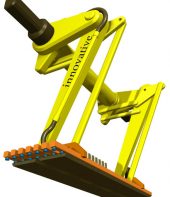
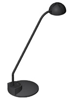
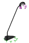
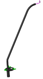
First step is to model the lamp. Being an expert CADsmen I made a model in a little under an hour. This model is similar to what the design engineer would start with. It is an assembly with 7 pieces; I have not included any of the electrical components as they should have no bearing on strength. Just for fun I’ve thrown in a quick rendered image because I thought it looked cool, and a picture of my lamp.
Cad Model |
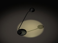
Rendered Image |
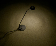
Actual Photo |
Second step is to boot up my favourite FEA software and import the assembly into it. Everything comes through OK so I move on to meshing (by now the industry has agreed on several standards that make this part fairly reliable). Third step is to mesh the model. Surprise, surprise, my program tells me it has problems with several of my solids, the error is not very descript and offers no suggestions. The problem is that, like 90% of components out there, there is simply too large of a range of geometry for the mesher to be able to handle. In this case the thin plastic moulding in the base plate has too much area, tight radii, and not enough thickness. So the recommended mesh size is doomed to failure. At this stage the solution is rarely to change the default mesh size. A good rule of thumb is to start with a good model and follow with the appropriate mesh. In this case the model has much more detail than is required to determine the strength of the light.
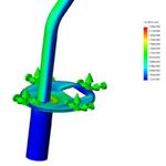
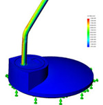 In the case of my lamp I removed all of the mould radii from the plastic base and now the mesher solves with the default settings, 24,494 elements, 60.3% of those with less than a 3:1 aspect ratio. I now continue on to add a fixed restraint to the base and a force of 5 lbs on the business end of the lamp. Brimming with confidence I hit the run analysis button and eagerly await the results. After 75 seconds the solution is complete. The stress plot tells me that there is a maximum of 13300psi stress in the main post and 0.3771” of deflection at the bulb. So I throw a couple of pretty pictures into a report and hand it to management. No problem with strength here, job well done!
Well, for a desk lamp maybe this is good enough, but if your component is worth doing a stress analysis on, then it is worth doing it properly. Lets back track and look at some common mistakes that happen throughout the entire industry.
Common Mistakes:
1) Know what you are analyzing and why!
With this lamp example there are only 24,494 elements but in most cases analyzing a whole assembly creates far too many elements resulting in long processing times and program crashes. In most cases you must refine the model in order to get an adequate mesh and to reduce solution times, BUT, refining the wrong area could hide serious problems. In order to make an effective FEA model you must know where the problem areas are in your model. Period.
A good engineer, with some experience in failure analysis will be able to just look at a model and see the weak locations. For more complex parts or assemblies it may be useful to do a preliminary analysis to find the points of interest (hand calculations are OK here!). For our lamp the weakest link is either the plastic piece that connects the arm to the base, or the arm itself. We can completely remove the lens and the base and all of the elements that go with them!
2) Pencils are still king in stress analysis
Every analysis should start with a pencil and paper (or your favourite math package/spread sheet) to determine an expected load range in the areas of interest. This gives you something to compare your FEA results with as a sanity check. Someone once told me:
“If your FEA results are close to your hand calcs then the FEA results are right, if they are different, then your hand calcs are right”
My opinion is that you should always do the hand calculations first so you are not tempted to fudge your calculations to match the FEA results, and it can help you highlight problem areas. In our case for the lamp arm, the moment load is 5lbs at 11in or 55in-lbf. The moment of inertia is 0.000923in^4 and the outside radius of the tube is 0.197”. Pump this through a beam bending formula and you get 11,738psi. That’s within 15% of our initial results, so in this case we are in the right ball park.
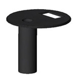 >The other area of interest is the arm mounting piece (shown here). I suspect that there will be a high stress zone, due to bending, between the arm mounting hole and the cut out for the switch (with a stress pattern mirrored about the mounting hole). The moment is the same 55in-lbf, but in this case the moment of inertia is only 0.0000451in^4 and the distance from the neutral axis is 0.03125. By simplifying the problem a little bit - into a beam fixed at both ends – (our plastic arm mount is vibration welded around its circumference to the lamp body) I calculate a stress of 20,454. Where was that stress in our first analysis? We’ll come back to this.
3) Get the right element type and the right size for the application
Element size matters, too big and you will get poor results, too small and the analysis can take hours, or even days. There are many rules of thumb for element size with respect to geometry type. Radii, bulk material, triangular/pointed geometry… all have ideal element densities/geometries determined by the type of element you are using in the analysis. In our case the primary rule that applies is that, with tetrahedral elements, you should have at least 2 elements per wall thickness in the area of interest. Using the default settings we barely have one!
4) The model is only as good as your boundary conditions
The boundary conditions in this case seem pretty straight forward, but that is rarely the case in real-world problems. Holding something fixed when it should be able to bend can completely change the outcome. With bad boundaries, stress peaks will be in the wrong spot, some will be amplified and others disappear all together. This often is (or should be) the most complicated part of the analysis and requires an in depth understanding of the mechanics of deformable solids. Unfortunately this is also where many FEA programs have gone to great lengths to streamline the process, lulling you into a false sense of security.
|
Simplified model with lense and base removed |
|
|
|
|
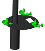 Lamp arm to base mounting piece
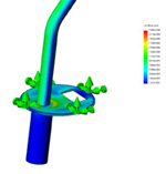 Final results, peak stress in Lamp Arm Mounting Piece
Lets go back and do the analysis a second time, avoiding these common pitfalls. Instead of analyzing the entire assembly we will look at only our two key components, the arm and the arm to body mounting piece. I apply the same load, but now I apply a fixed support around the circumference of the mounting piece (an analog to the fact that it is welded to the base). In the two areas of interest that I have identified using hand calculations I will cut the mesh size down to ½ the wall thickness. So now I have 50,000 elements, more than the first run for sure, but still easily handled and the accuracy will be significantly improved.
After 97 seconds of run time whoa! Different picture! Now the stress in the arm is only 10,800 psi and the stress in the arm mounting piece is up to 23,060psi.
This analysis shows that the mounting piece that looked fine in the first analysis is now well past its yield point (being plastic). What changed between the analyses? The problem is with boundary conditions…sort of. In the first example the element mesher saw that the mounting piece is close to the base plate and meshed them as a single solid. This effectively added a fixed boundary condition to the bottom of the mounting piece, greatly increasing its load carrying capacity. Our second example removed this problem and showed what is truly happening. Based on the fact that I had done my stress analysis first I was not surprised with the results; look back and you will see that not only did I predict both high stress locations but both of my hand calculations were within 15% of the FEA results. Not bad for a method that is 300 years old! This highlights how much an incorrect boundary condition can affect your results, whether it was added intentionally or not.
This brings me to my final point. As analysis engineers, we must match the right analysis tool to the job. From a customer perspective this one is a no brainer. It took me several hours to get a good analysis from FEA (including modelling) and only 15 minutes to do hand calculations. In this simple case, the extra 15% accuracy is just not justified by the expense. This is not uncommon, when I am wearing my design engineer hat approximately 80-90% of my analyses are done in my favourite spread sheet program. FEA should be reserved for the few gems of systems or components which defy other techniques. As a customer, make sure you don’t ask your engineering resource for an FEA, ask for an analysis, in many cases it can cost 50% less!
This article was authored by Bradley Woodward. Mr. Woodward has been a mechanical engineer since 2006 with experience in analysis and design. He has a broad range of analysis experience ranging from simple mechanical components to thermal cycle fatigue analysis of gas turbines.